Sidre Interaction with Conduit
Internally, Sidre uses the in-memory data description capabilities of Conduit. Sidre also leverages Conduit to facilitate data exchange, demonstrated here as applied to visualization. The following discussion gives a basic overview of Sidre’s capabilities when combined with Conduit. Please see the reference documentation for more details.
Mesh Blueprint
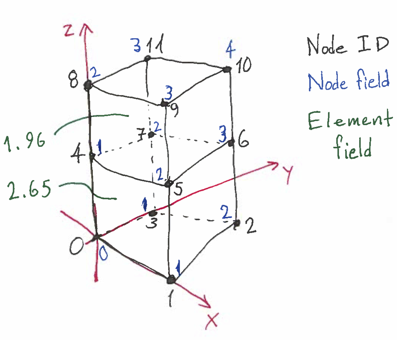
The Mesh Blueprint is a data exchange protocol supported by Conduit, consisting of a properly-structured Datastore saved as an HDF5 or JSON file and a Conduit index file. The Blueprint can accomodate structured or unstructured meshes, with node- or element-centered fields. The following example shows how to create a Blueprint-conforming Datastore containing two unstructured adjacent hexahedrons with one node-centered field and one element-centered field. In the diagram, nodes are labeled in black, the node-centered field values are in blue, and the element-centered field values are in green.
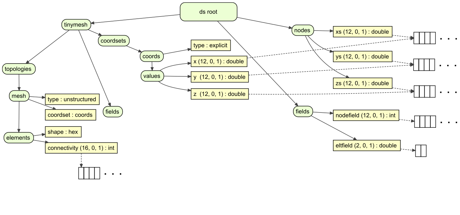
A simulation organizes its Sidre data as the code design dictates. Here is a simple example.
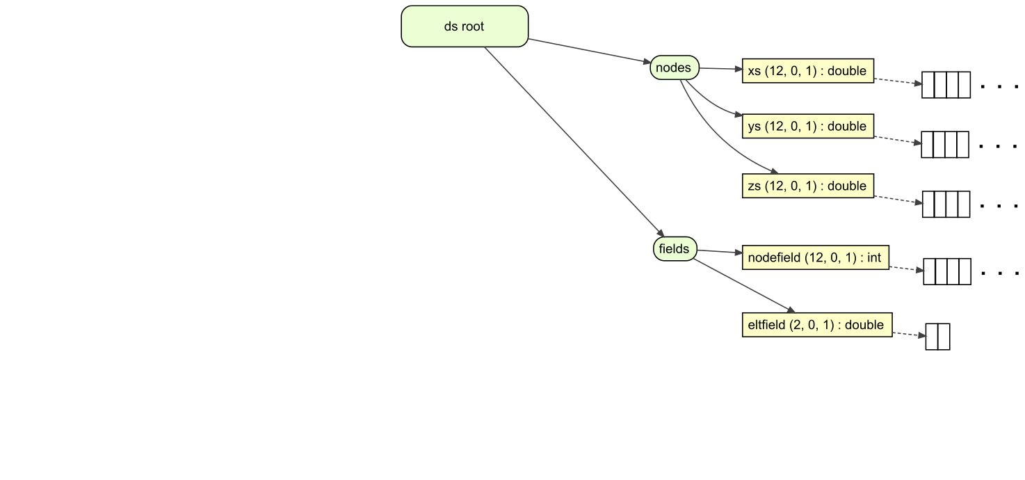
Here is the code to create that Dataset ds.
  DataStore* ds = new DataStore();

  int nodecount = 12;
  int elementcount = 2;

  // Create views and buffers to hold node positions and field values
  Group* nodes = ds->getRoot()->createGroup("nodes");
  View* xs = nodes->createViewAndAllocate("xs", sidre::DOUBLE_ID, nodecount);
  View* ys = nodes->createViewAndAllocate("ys", sidre::DOUBLE_ID, nodecount);
  View* zs = nodes->createViewAndAllocate("zs", sidre::DOUBLE_ID, nodecount);

  Group* fields = ds->getRoot()->createGroup("fields");
  View* nodefield =
    fields->createViewAndAllocate("nodefield", sidre::INT_ID, nodecount);
  View* eltfield =
    fields->createViewAndAllocate("eltfield", sidre::DOUBLE_ID, elementcount);

  // Set node position for two adjacent hexahedrons
  double* xptr = xs->getArray();
  double* yptr = ys->getArray();
  double* zptr = zs->getArray();
  for (int pos = 0 ; pos < nodecount ; ++pos)
  {
    xptr[pos] = ((pos + 1) / 2) % 2;
    yptr[pos] = (pos / 2) % 2;
    zptr[pos] = pos / 4;
  }

  // Assign a value to the node field
  int* nf = nodefield->getArray();
  for (int pos = 0 ; pos < nodecount ; ++pos)
  {
    nf[pos] = static_cast<int>(xptr[pos] + yptr[pos] + zptr[pos]);
  }
  // and to the element field.
  double* ef = eltfield->getArray();
  // There are only two elements.
  ef[0] = 2.65;
  ef[1] = 1.96;

  return ds;
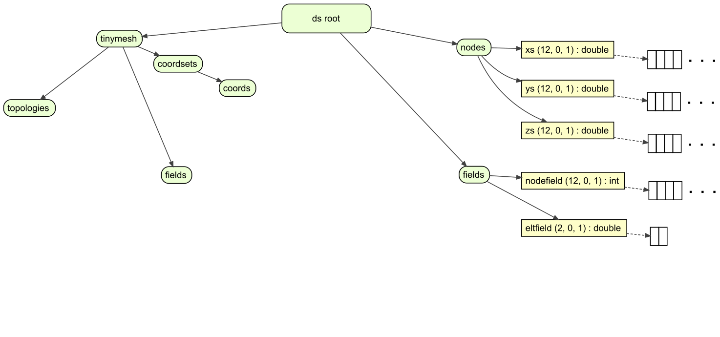
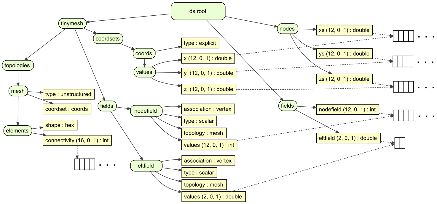
To use the Mesh Blueprint, make a new Group tinymesh conforming to the protocol.
The structure of the conforming Group is shown below (summarizing
the Mesh Blueprint
documentation).
First build top-level groups required by the Blueprint.
  // Conduit needs a specific hierarchy.
  // We'll make a new DataStore with that hierarchy, pointing at the
  // application's data.
  std::string mesh_name = "tinymesh";

  // The Conduit specifies top-level groups:
  Group* mroot = ds->getRoot()->createGroup(mesh_name);
  Group* coords = mroot->createGroup("coordsets/coords");
  Group* topos = mroot->createGroup("topologies");
  // no material sets in this example
  Group* fields = mroot->createGroup("fields");
  // no adjacency sets in this (single-domain) example
Add the node coordinates. The Views under tinymesh will point to the
same Buffers that were created for the Views under nodes
so that tinymesh can use the data without any new allocation or copying.
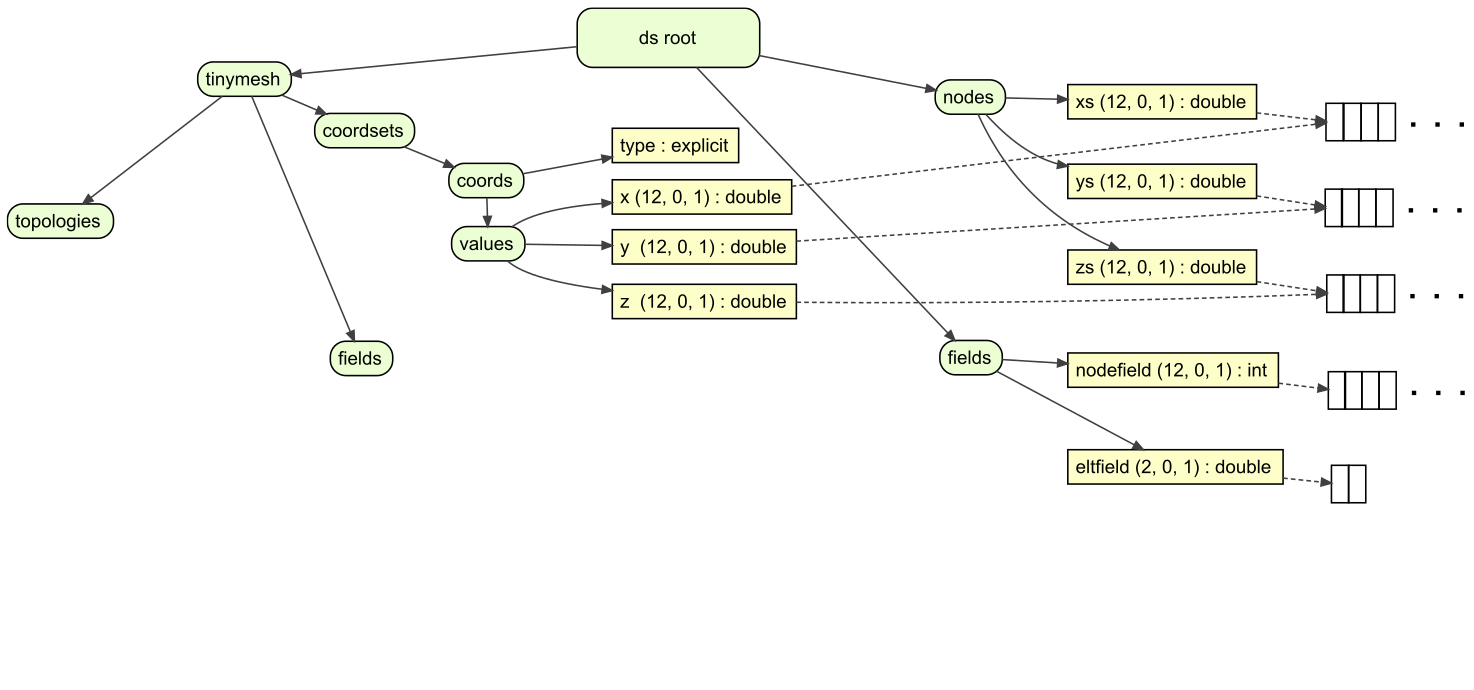
  // Set up the coordinates as Mesh Blueprint requires
  coords->createViewString("type", "explicit");
  // We use prior knowledge of the layout of the original datastore
  View* origv = ds->getRoot()->getView("nodes/xs");
  Group* conduitval = coords->createGroup("values");
  conduitval->createView("x", sidre::DOUBLE_ID,
                         origv->getNumElements(),
                         origv->getBuffer());
  origv = ds->getRoot()->getView("nodes/ys");
  conduitval->createView("y", sidre::DOUBLE_ID,
                         origv->getNumElements(),
                         origv->getBuffer());
  origv = ds->getRoot()->getView("nodes/zs");
  conduitval->createView("z", sidre::DOUBLE_ID,
                         origv->getNumElements(),
                         origv->getBuffer());
Arrange the nodes into elements. Each simulation has its own knowledge of topology. This tiny example didn’t previously encode topology, so we must explicitly specify it.
  // Sew the nodes together into the two hexahedra, using prior knowledge.
  Group* connmesh = topos->createGroup("mesh");
  connmesh->createViewString("type", "unstructured");
  connmesh->createViewString("coordset", "coords");
  Group* elts = connmesh->createGroup("elements");
  elts->createViewString("shape", "hex");

  // We have two eight-node hex elements, so we need 2 * 8 = 16 ints.
  View* connectivity =
    elts->createViewAndAllocate("connectivity", sidre::INT_ID, 16);

  // The Mesh Blueprint connectivity array for a hexahedron lists four nodes on
  // one face arranged by right-hand rule to indicate a normal pointing into
  // the element, then the four nodes of the opposite face arranged to point
  // the normal the same way (out of the element).  This is the same as for
  // a VTK_HEXAHEDRON.  See
  // https://www.vtk.org/wp-content/uploads/2015/04/file-formats.pdf.

  int* c = connectivity->getArray();

  // First hex.  In this example, the Blueprint node ordering matches the
  // dataset layout.  This is fortuitous but not required.
  c[0] = 0; c[1] = 1; c[2] = 2; c[3] = 3;
  c[4] = 4; c[5] = 5; c[6] = 6; c[7] = 7;

  // Second and last hex
  c[8] = 4; c[9] = 5; c[10] = 6; c[11] = 7;
  c[12] = 8; c[13] = 9; c[14] = 10; c[15] = 11;
Link the fields into tinymesh. As with the node positions, the Views
point to the existing Buffers containing the field data.
  // Set up the node-centered field
  // Get the original data
  View* origv = ds->getRoot()->getView("fields/nodefield");
  Group* nodefield = fields->createGroup("nodefield");
  nodefield->createViewString("association", "vertex");
  nodefield->createViewString("type", "scalar");
  nodefield->createViewString("topology", "mesh");
  nodefield->createView("values", sidre::INT_ID,
                        origv->getNumElements(),
                        origv->getBuffer());

  // Set up the element-centered field
  // Get the original data
  origv = ds->getRoot()->getView("fields/eltfield");
  Group* eltfield = fields->createGroup("eltfield");
  eltfield->createViewString("association", "element");
  eltfield->createViewString("type", "scalar");
  eltfield->createViewString("topology", "mesh");
  eltfield->createView("values", sidre::DOUBLE_ID,
                       origv->getNumElements(),
                       origv->getBuffer());
Conduit includes a verify method to test if the structure
of the tinymesh conforms to the Mesh Blueprint. This is valuable for writing and
debugging data adapters.
Once the Datastore is properly structured, save it, then use Conduit to save the
index file (ending with .root). This toy data set is small enough that we can
choose to save it as JSON.
  conduit::Node info, mesh_node, root_node;
  ds->getRoot()->createNativeLayout(mesh_node);
  std::string bp_protocol = "mesh";
  if (conduit::blueprint::verify(bp_protocol, mesh_node[mesh_name], info))
  {
    // Generate the Conduit index
    conduit::Node & index = root_node["blueprint_index"];
    conduit::blueprint::mesh::generate_index(mesh_node[mesh_name],
                                             mesh_name,
                                             1,
                                             index[mesh_name]);

    std::string root_output_path = mesh_name + ".root";
    std::string output_path = mesh_name + ".json";

    root_node["protocol/name"] = "json";
    root_node["protocol/version"] = "0.1";
    root_node["number_of_files"] = 1;
    root_node["number_of_trees"] = 1;
    root_node["file_pattern"] = output_path;
    root_node["tree_pattern"] = "/";

    // Now save both the index and the data set
    conduit::relay::io::save(root_node, root_output_path, "json");
    conduit::relay::io::save(mesh_node, output_path, "json");
  }
  else
  {
    std::cout << "does not conform to Mesh Blueprint: ";
    info.print();
    std::cout << std::endl;
  }
The code listed above produces the files tinymesh.json and tinymesh.root. Any code that uses Mesh Blueprint can open and use this pair of files.
The DataStore also contains a method that can automatically generate the Blueprint index within a Sidre Group rather than calling directly into Conduit. Set up a mesh similarly to the example above.
  // Conduit needs a specific hierarchy.
  // We'll make a new Group with that hierarchy, pointing at the
  // application's data.
  std::string domain_name = "domain";
  std::string domain_location = "domain_data/" + domain_name;
  std::string mesh_name = "mesh";
  std::string domain_mesh = domain_location + "/" + mesh_name;

  Group* mroot = ds->getRoot()->createGroup(domain_location);
  Group* coords = mroot->createGroup(mesh_name + "/coordsets/coords");
  Group* topos = mroot->createGroup(mesh_name + "/topologies");
  // no material sets in this example
  Group* fields = mroot->createGroup(mesh_name + "/fields");
  // no adjacency sets in this (single-domain) example
Then use DataStore::generateBlueprintIndex to generate the index within
a Group held by the DataStore. Then additional data needed in the root file
can be added and saved using Sidre I/O calls.
  conduit::Node info, mesh_node, root_node;
  ds->getRoot()->createNativeLayout(mesh_node);
  std::string bp_protocol = "mesh";
  if (conduit::blueprint::verify(bp_protocol, mesh_node[domain_mesh], info))
  {
    std::string bp("rootfile_data/blueprint_index/automesh");

    ds->generateBlueprintIndex(domain_mesh, mesh_name, bp, 1);

    Group* rootfile_grp = ds->getRoot()->getGroup("rootfile_data");
    rootfile_grp->createViewString("protocol/name", "json");
    rootfile_grp->createViewString("protocol/version", "0.1");
    rootfile_grp->createViewScalar("number_of_files", 1);
    rootfile_grp->createViewScalar("number_of_trees", 1);
    rootfile_grp->createViewScalar("file_pattern", "bpgen.json");
    rootfile_grp->createViewScalar("tree_pattern", "/domain");
    rootfile_grp->save("bpgen.root", "json");

    ds->getRoot()->getGroup("domain_data")->save("bpgen.json", "json");
  }
  else
  {
    std::cout << "does not conform to Mesh Blueprint: ";
    info.print();
    std::cout << std::endl;
  }
Additionally, the Sidre Parallel I/O (SPIO) class IOManager provides a
method that both generates a Blueprint index and adds it to a root file.
Using the same mesh data from the last example, first write out all of the
parallel data using IOManager::write. This will output to files all of
the data for all domains, and will also create a basic root file. Then
IOManager::writeBlueprintIndexToRootFile can be used to generate the
Blueprint index and add it to the root file. This is currently only
implemented to work with the sidre_hdf5 I/O protocol.
  IOManager writer(MPI_COMM_WORLD);

  conduit::Node info, mesh_node, root_node;
  ds->getRoot()->createNativeLayout(mesh_node);
  std::string bp_protocol = "mesh";
  if (conduit::blueprint::verify(bp_protocol, mesh_node[domain_mesh], info))
  {

    std::string bp_rootfile("bpspio.root");

    writer.write(ds->getRoot()->getGroup(
                   domain_location), 1, "bpspio", "sidre_hdf5");

    writer.writeBlueprintIndexToRootFile(ds, domain_mesh, bp_rootfile,
                                         mesh_name);

  }
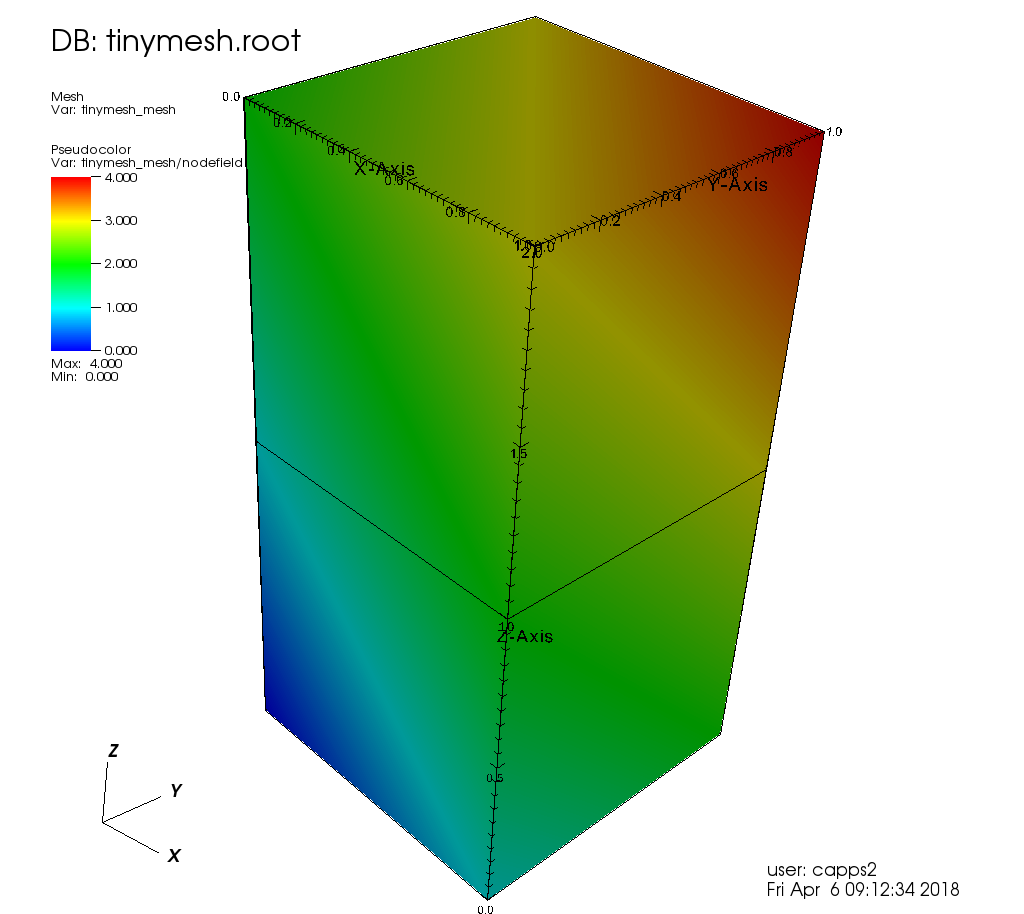
Data Visualization
The VisIt tool can read in a Blueprint, interpret the index file, and sensibly display the data contained in the data file. Starting from version 2.13.1, VisIt can open a .root file just like any other data file. VisIt produced the following image from the Mesh Blueprint file saved above.
Conduit is also a foundational building block for the Ascent project, which provides a powerful data analytics and visualization facility (without copying memory) to distributed-memory simulation codes.