Extraction
The BUMP component provides multiple algorithms for extracting data from Blueprint meshes where the output geometry consists of fragments created from the input mesh’s zones, including:
axom::bump::extraction::ClipField
axom::bump::extraction::CutField
axom::bump::extraction::PlaneSlice
The algorithms are implemented as classes with template parameters that set policies that determine where the algorithms will execute, which coordset and topology types they support, and how they perform intersection. The input to an algorithm is a Blueprint mesh. When instantiated with coordset and topology views appropriate for the input data, the algorithm can operate on a wide variety of mesh types. This includes 2D/3D structured and unstructured topologies that can be represented using finite elements.
Algorithms are called using a pattern where the algorithm is first
instantiated (using execution space, topology view, and coordset view parameters),
followed by calling an execute() method. The execute()
method accepts Conduit nodes for the input Blueprint mesh, any options, and the output mesh.
Inputs
BUMP’s extraction algorithms accept a Conduit node containing various options that influence how the algorithm operates. The algorithms copy the options node to the memory space where it will be used to support options that are accessed on a device. This enables algorithms to use data arrays on device.
The following table provides the options that are common to all algorithms:
Option |
Description |
|---|---|
|
If inside=1 and outside=1 then a color field is generated so it is possible to tell apart regions of the clip output that were inside or outside the clip boundary. This field permits the user to change the name of the color field, which is called “color” by default. |
|
The name of the new coordset in the output mesh. If it is not provided, the output coordset will have the same name as the input coordset. |
|
The fields node lets the caller provide a list of field names that will be processed and added to the output mesh. The form is currentName:newName. If the fields node is not given, the algorithm will process all input fields. If the fields node is empty then no fields will be processed. |
|
Indicates to the clipping algorithm that it should preserve zone fragments that were “inside” the clip boundary. Set to 1 to enable, 0 to disable. The algorithm will generate these fragments by default. |
|
The name of the field in which to store the original elements map. The default is “originalElements”. |
|
Indicates to the clipping algorithm that it should preserve zone fragments “outside” the clip boundary. Set to 1 to enable, 0 to disable. These fragments are not on by default. |
|
An optional argument that provides a list of zone ids on which to operate. The output mesh will only have contributions from zone numbers in this list, if it is given. |
|
The name of the new topology in the output mesh. If it is not provided, the output topology will have the same name as the input topology. |
ClipField
The ClipField class with its default intersection policy breaks a mesh’s zones into
fragments, using an isosurface defined by a field where it equals a target clip value,
to select and cut the mesh’s zones. The surface divides the mesh into 2 colors, either of
which can be selected. Whole zones that are selected become zones in the new mesh, as do
any zone fragments arising from zones that are cut by the surface. Zone fragments have the
same topological dimension as the input zones (2D zones make 2D fragments and 3D zones make
3D fragments).
To use the ClipField class, one must have Blueprint data with at least one vertex-associated
field. Views for the coordset and topology are created and their types are used to instantiate
a ClipField object. The ClipField constructor takes a Conduit node for the input Blueprint mesh, a Conduit
node that contains the options, and a 3rd output Conduit node that will contain the clipped
mesh and fields. The input mesh node needs to contain data arrays for coordinates, mesh
topology, and fields. These data must exist in the memory space of the targeted device.
Other Conduit nodes that contain strings or single numbers that can fit within a Conduit
node are safe remaining in host memory. If the mesh is not in the desired memory space, it
can be moved using axom::bump::utilities::copy().
Option |
Description |
|---|---|
|
A required string argument that specifies the name of the field that is used for clipping. At present, the field must be a vertex-associated field. |
|
An optional numeric argument that specifies the value in the field at which the clip boundary is defined. The default is 0. |
#include "axom/bump.hpp"

// Set up views for the mesh in deviceRoot node.
auto coordsetView = axom::bump::views::make_rectilinear_coordset<float, 3>::view(deviceRoot["coordsets/coords"]);
auto topologyView = axom::bump::views::make_rectilinear_topology<3>::view(deviceRoot["topologies/Mesh"]);

// Make a clipper.
using CoordsetView = decltype(coordsetView);
using TopologyView = decltype(topologyView);
using Clip = axom::bump::extraction::ClipField<axom::SEQ_EXEC, TopologyView, CoordsetView>;
Clip clipper(topologyView, coordsetView);

// Run the clip algorithm
conduit::Node options;
options["field"] = "data";
options["value"] = 3.5;
options["outside"] = 1;
options["inside"] = 0;
clipper.execute(deviceRoot, options, clipOutput);
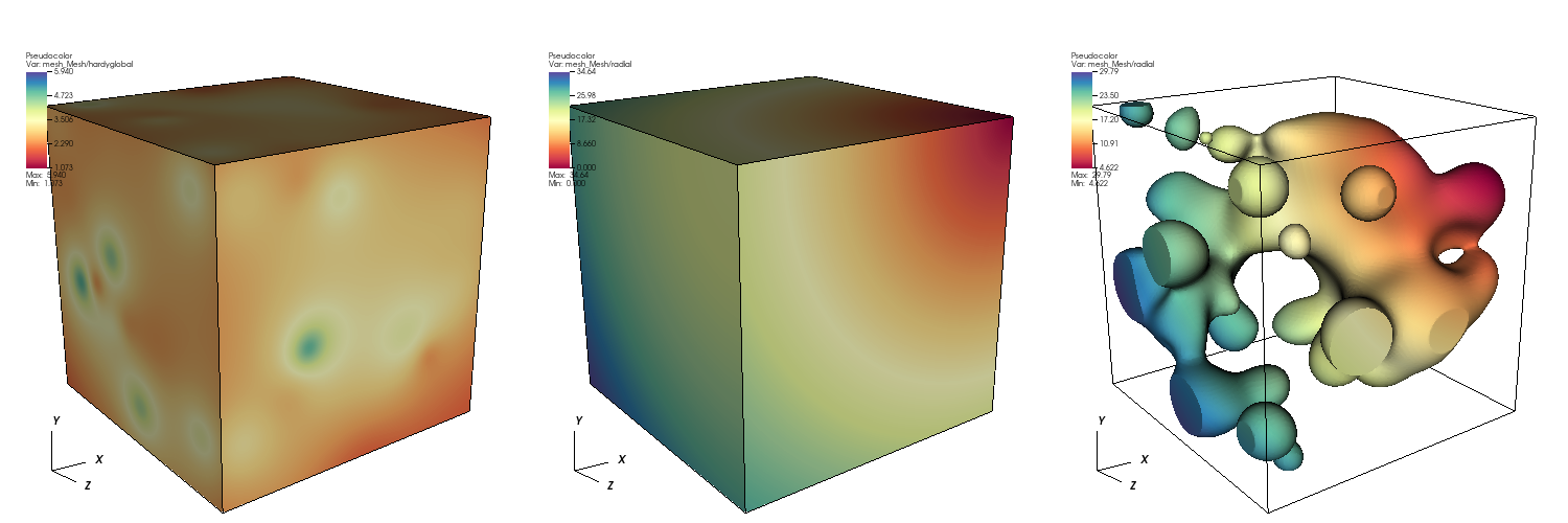
Fig. 1 Diagram showing original mesh colored by clipping field (left), original mesh colored by a radial field (middle), and the clipped mesh colored by the radial field (right).
Intersectors
An intersector is a policy class that is passed as a template argument to ClipField. The
intersector determines how the ClipField algorithm will generate intersection cases, for
each zone in the mesh. The ClipField algorithm default intersector uses a field to determine clip
cases, resulting in isosurface behavior for the geometry intersections. Alternative intersectors
can be provided to achieve other types of intersections.
CutField
The CutField class with its default intersection policy performs an isosurface. Given 2D input,
the output will consist of 1D line segments. For 3D input, the output will consist of 2D polygonal
surfaces.
Option |
Description |
|---|---|
|
A required string argument that specifies the name of the field that is used for clipping. At present, the field must be a vertex-associated field. |
|
An optional numeric argument that specifies the value in the field at which the clip boundary is defined. The default is 0. |
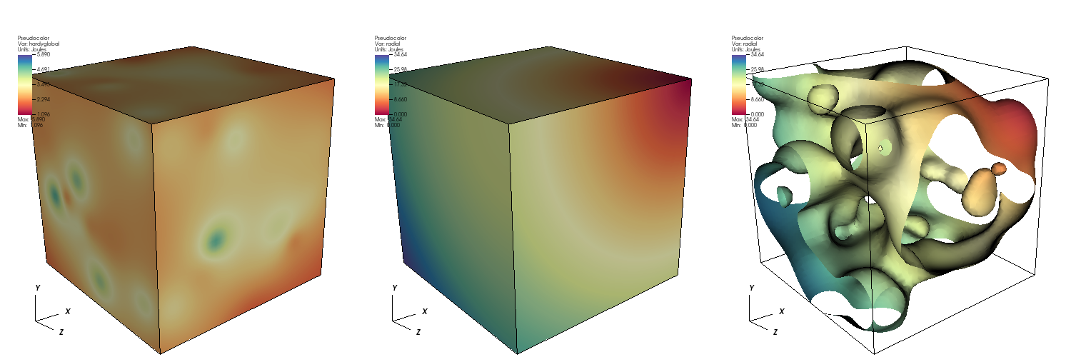
Fig. 2 Diagram showing original mesh colored by cutting field (left), original mesh colored by a radial field (middle), and the cut mesh colored by the radial field (right).
PlaneSlice
The PlaneSlice class with its default intersection policy slices the input geometry using a plane.
The algorithm works in 2D and 3D. For 2D, the plane “origin” and “normal” contain 2 components that describe
a line and the output will consist of line segments along that line. For 3D, the “origin” and “normal”
contain 3 components that describe a plane. The output will contain polygonal shapes that cover the
intersection of the slice plane with the input mesh.
Option |
Description |
|---|---|
|
A required array argument that specifies the plane origin. There must be 2 or 3 array elements, depending on the topological dimension of the Blueprint mesh being sliced. |
|
A required array argument that specifies the plane normal, which determines the slice plane orientation. There must be 2 or 3 array elements, depending on the topological dimension of the Blueprint mesh being sliced. |
|
A required string argument containing the name of the Blueprint topology to slice. |
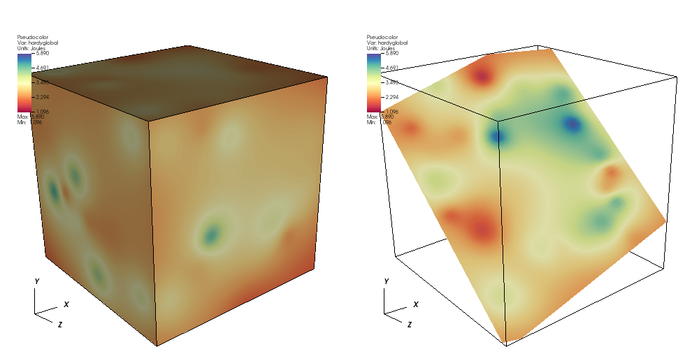
Fig. 3 Diagram showing original mesh colored by a field (left), and the sliced mesh colored by the a field (right).